
EN
EN
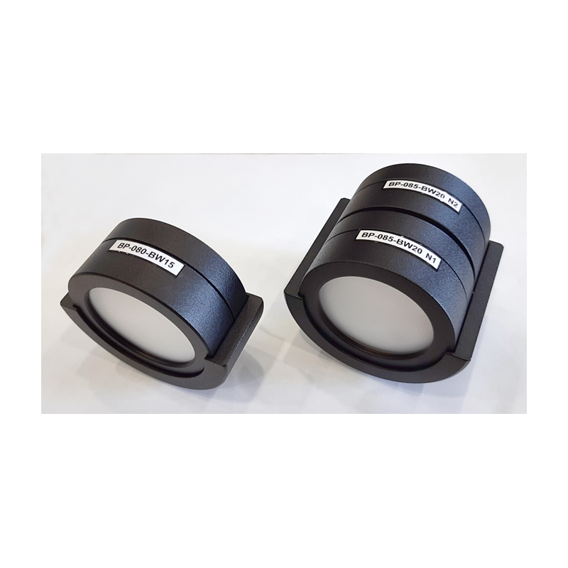
High-Quality THz Bandpass Filter
一、Product Introduction
THz Bandpass Filters (hereinafter referred to as Filters) are designed for spectral filtering of terahertz electromagnetic radiation within the electromagnetic spectrum. The Filters deliver high transmittance for wavelengths falling within a specific spectral range while effectively blocking transmission of wavelengths outside this band.They can be applied in quasi-optical spectral analysis systems to measure or control radiation from broadband long-wavelength terahertz sources, eliminate or select frequency harmonics in radiation spectra, and suppress unwanted spectral components in incident radiation that may saturate terahertz detectors.
Each filter consists of a set of specially designed perforated metal foils (1) (mesh), mounted on a circular frame housed within a cylindrical metal housing (2) with an outer (free) diameter of 69 mm (Figure 1). The metal housing (2) is coated with black protective paint. To prevent dust from entering the interior of the filter, a thin, high-frequency transparent polymer film (3) protects both sides of the 52 mm optical (open) aperture. A label (4) is affixed to the filter housing (2), indicating the filter model number (see Table 1 in Section 2).
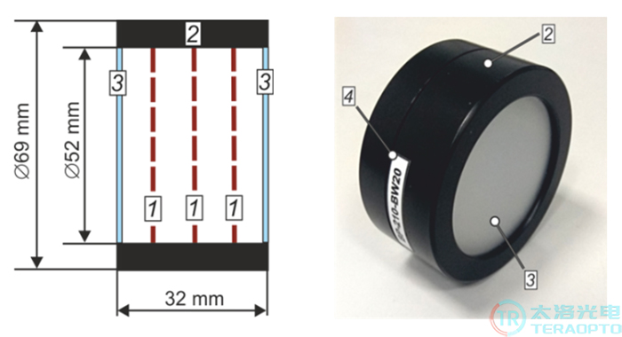
Figure 1. Structure (a) and Appearance (b) of the THz filter
1.1Main Features of THz Bandpass Filters
● The Maximum Selectable Center Frequency Range:νmax 0.07~3THz
● THz Filter Relative Bandwidth: 15%~20%
● Peak Transmittance: 84~97%
● Out-Of-Band Blocking: 23dB~40 dB
● Standard Clear Aperture: ø50 mm
● Polarization-Insensitive
● Vacuum-Compatible
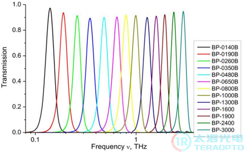
The graph shows the measured spectral transmittance of standard THz Bandpass Filters (tested with BWO + Fourier-transform infrared spectrometer)
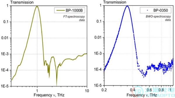
The figure illustrates the out-of-band terahertz wave suppression capability of standard THz Bandpass Filter
1.2 .Customization Options for THz Bandpass Filters
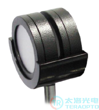
● Optional auxiliary mounting brackets with diameters:10~75 mm
● Customizable νmax and △ν/νmax值
● Enhanced out-of-band rejection
● Multi-Bandpass configurations
● Polarization discrimination functionality
● Low-Temperature operation compatibility
An auxiliary bracket enables filter mounting on optical benches. Two nested slots allow two filters to be stacked sequentially for improved out-of-band attenuation.
Brackets can be customized per customer requirements.
Standard THz Bandpass Filter Models
Products Name | Filter Model | Center Frequency νmax(THz)* | Peak Transmittance Tmax** | Relative Bandwidth △ν/νmax*** | Out-Of-Band Spect- ral Leaage **** |
THz Bandpass Filter | BP-0075 | 0.075 | 0.95 | 0.15 | ≤10-4 |
THz Bandpass Filter | BP-0094 | 0.094 | 0.95 | 0.15 | ≤10-4 |
THz Bandpass Filter | BP-0100 | 0.100 | 0.95 | 0.15 | ≤10-4 |
THz Bandpass Filter | BP-0140 | 0.140 | 0.94 | 0.15 | ≤10-4 |
THz Bandpass Filter | BP-0140B | 0.140 | 0.94 | 0.20 | ≤2*10-4 |
THz Bandpass Filter | BP-0150B | 0.150 | 0.94 | 0.20 | ≤2*10-4 |
THz Bandpass Filter | BP-0190B | 0.190 | 0.94 | 0.20 | ≤2*10-4 |
THz Bandpass Filter | BP-0220 | 0.220 | 0.94 | 0.15 | ≤2*10-4 |
THz Bandpass Filter | BP-0220B | 0.220 | 0.94 | 0.20 | ≤2*10-4 |
THz Bandpass Filter | BP-0260B | 0.260 | 0.93 | 0.20 | ≤3*10-4 |
THz Bandpass Filter | BP-0300B | 0.300 | 0.92 | 0.20 | ≤3*10-4 |
THz Bandpass Filter | BP-0350 | 0.350 | 0.91 | 0.15 | ≤4*10-4 |
THz Bandpass Filter | BP-0350B | 0.350 | 0.92 | 0.20 | ≤4*10-4 |
THz Bandpass Filter | BP-0480B | 0.480 | 0.92 | 0.20 | ≤5*10-4 |
THz Bandpass Filter | BP-0500B | 0.500 | 0.92 | 0.20 | ≤5*10-4 |
THz Bandpass Filter | BP-0600B | 0.600 | 0.92 | 0.20 | ≤5*10-4 |
THz Bandpass Filter | BP-0650 | 0.650 | 0.90 | 0.15 | ≤5*10-4 |
THz Bandpass Filter | BP-0650B | 0.650 | 0.92 | 0.20 | ≤5*10-4 |
THz Bandpass Filter | BP-0800 | 0.800 | 0.90 | 0.15 | ≤6*10-4 |
THz Bandpass Filter | BP-0800B | 0.800 | 0.92 | 0.20 | ≤6*10-4 |
THz Bandpass Filter | BP-1000 | 1.000 | 0.90 | 0.15 | ≤8*10-4 |
THz Bandpass Filter | BP-1000B | 1.000 | 0.91 | 0.20 | ≤10*10-4 |
THz Bandpass Filter | BP-1300 | 1.300 | 0.89 | 0.15 | ≤10*10-4 |
THz Bandpass Filter | BP-1300B | 1.300 | 0.91 | 0.20 | ≤30*10-4 |
THz Bandpass Filter | BP-1600 | 1.600 | 0.89 | 0.15 | ≤10*10-4 |
THz Bandpass Filter | BP-1600B | 1.600 | 0.91 | 0.20 | ≤30*10-4 |
THz Bandpass Filter | BP-1900 | 1.900 | 0.88 | 0.15 | ≤30*10-4 |
THz Bandpass Filter | BP-2400 | 2.400 | 0.88 | 0.15 | ≤40*10-4 |
THz Bandpass Filter | BP-3000 | 3.000 | 0.88 | 0.15 | ≤50*10-4 |
*Tolerance±1%;**Tolerance±1%;****Frequency estimation 1.5-10*νmax;****Tolerance±1%;,Bandwidth is estimated under the standard 0.5*Tmax(FWHM).
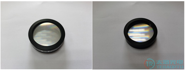
Physical photo of the product
Precautions
The filter is fragile. Do not drop it!
Furthermore, as the protective film (3) is very thin, do not touch it with your fingers or hard objects! If you notice dust particles on the surface of the protective film and wish to remove them, please use a soft-bristled brush (preferably a squirrel brush).
Notice
Transmitting the filter to the end user may require a third party (such as customs officers, transportation company agents, etc.) to inspect the product. To avoid accidentally damaging the terahertz-transparent polymer film (3) of the filter during the inspection process, the surface of the filter is protected by an additional transparent plastic cover (Figure 2). The cover is fixed to the filter housing with foam plastic.
The plastic protective cover is only used when delivering the filter to the end user. Before starting to use the filter, the cover must be removed.
If after removing the foam rubber band you find any traces of adhesive layer on the filter housing, please carefully remove it (for example, using a sticky tape or a soft cloth soaked in alcohol).
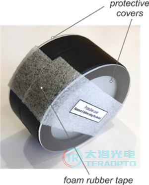
Figure 2. Photo of the filter with an auxiliary protective plastic cover.
1.3Filter Support
In order to install the filter on the optical table or optical guide rail, an auxiliary metal bracket is provided with the filter. This bracket comes in two types: it can be used to place one or two filters separately (see Figures 3 and 4).
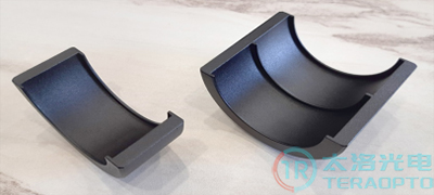
Figure 3. Photo of the filter holder (top view): On the left is 1 filter, and on the right are 2 filters.
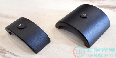
Figure 4. Photo of the filter holder (bottom view): On the left is 1 filter, and on the right are 2 filters.
The surface of the bracket is coated with black protective paint, and at the bottom there is an M5 threaded blind hole, which can fix the filter onto the optical column. Due to the raised surface of the bracket, when using it, the filter can be safely fixed onto the bracket (Figure 5).
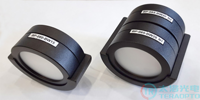
Figure 5. Photos showing the single filter (left) and the double filter (right) installed on the single filter and double filter brackets respectively.
二、Technical Parameters And Test Data
The filters included in the current delivery batch have the following technical parameters:
This device consists of five filters of four different types. The central frequency nmax, relative bandwidth Dn/nmax (FWHM), and quantity are listed in Table 1:
Table 1:
Model | nmax, THz | Dn/nmax, % | Quantity, pc. |
BP-085-BW20 | 0.85 | 20 | 2 |
BP-100-BW20 | 1.0 | 20 | 1 |
BP-150-BW17 | 1.5 | 17 | 1 |
BP-255-BW18 | 2.55 | 18 | 1 |
Peak power transmission maximum value:82-92%。
The allowable deviation of nmax:± 0.5-2%*。
Dn/nmax allowable deviation:± 0.5-2%*
Transmission outside the passband:< -35 dB。
Working environment: Room temperature**。
The experimental terahertz power emission spectrum of the filter is shown in Figure 10-13. The TDS data was obtained using a homemade time-domain spectrometer within the range of 0.1 - 2.6 terahertz, while the FTS data was acquired using the vacuum Fourier spectrometer Bruker Vertex 80v and a room-temperature DTGS detector. The illustration shows the actual parameters of the filter derived from the experimental spectrum.(nmax, Dn/nmax, Tmax)。
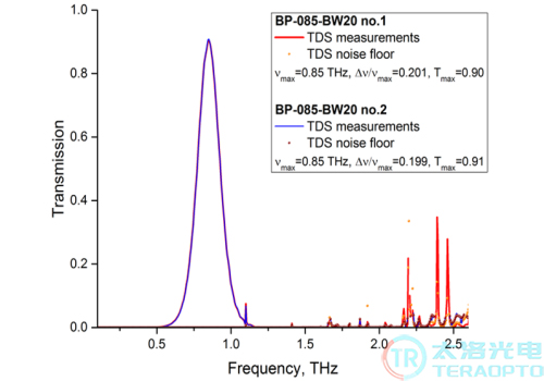
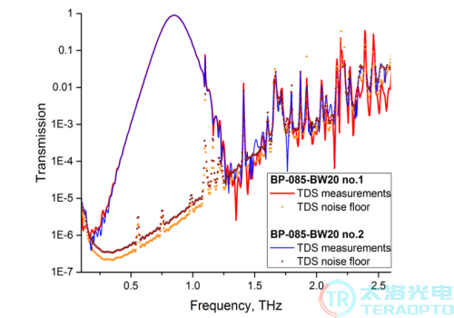
Figure 10: Linear-scale (top) and logarithmic-scale (bottom) TDS transmittance spectra of BP-085-BW20 filters
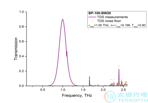
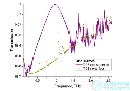
Figure 11: Linear-scale (top) and logarithmic-scale (bottom) TDS transmittance spectra of BP-100-BW20 filter
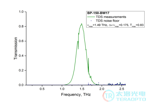
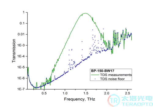
Figure 12: Linear-scale (top) and logarithmic-scale (bottom) TDS transmittance spectra of BP-150-BW17 filter
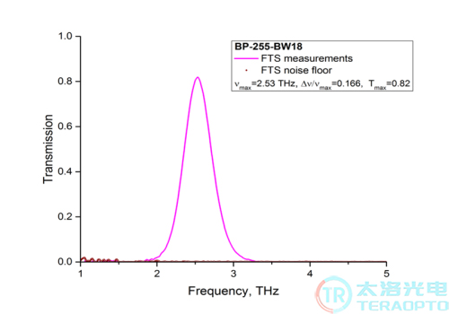
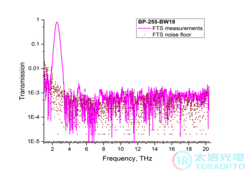
Figure 13: Linear-scale (top) and logarithmic-scale (bottom) FTS transmittance spectra of BP-255-BW18 filter****。
***Note that the spectral leakage near the second and third harmonics of the filter's fundamental frequency is caused by the instrument error in Fourier transform measurement.
*Due to manufacturing tolerances, the allowable deviation of nmax and Dn/nmax for low-frequency filters (nmax £ 1 THz) is typically £0.5%, while for high-frequency filters (nmax > 1 THz), the allowable deviation increases to 2%.
**If you need a special filter for low-temperature operation, please contact the supplier.
三、Storage and Transportation
Using the plastic boxes as described in Paragraph 1.3 can ensure the safe storage and transportation of the filters. To prevent the filters from being damaged, when the filters are placed in the plastic boxes, please avoid strong mechanical impacts and the flipping of the boxes.
During the transportation process, please abide by the current requirements and safety measures for the specific type of transportation.
The manufacturer shall not be held responsible for any product defects or malfunctions resulting from violations of storage and transportation regulations.