
EN
EN
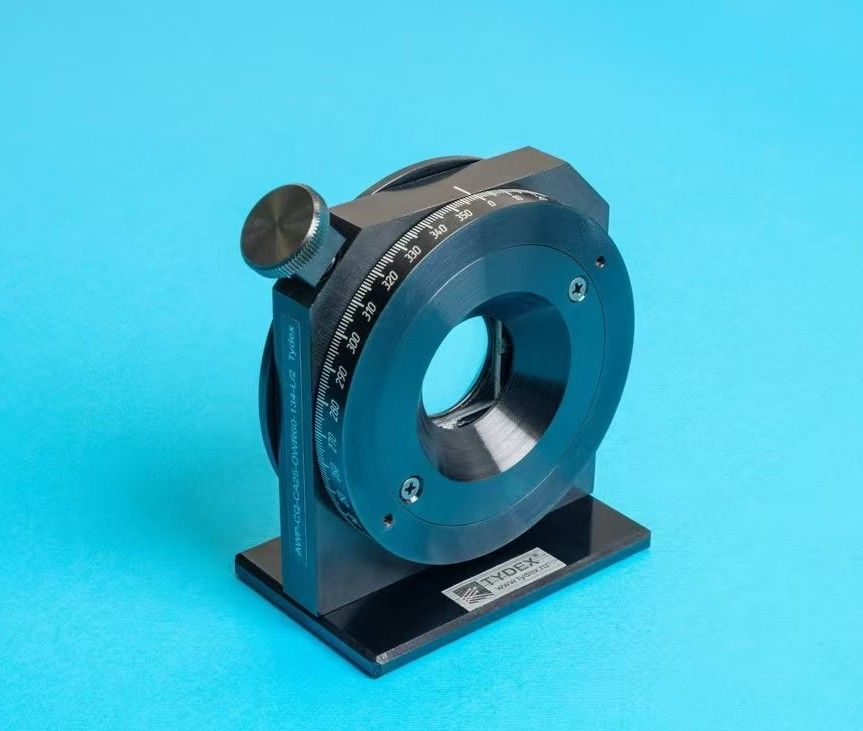
Broad‑band THz waveplate Achromatic THz waveplate THz waveplate
A THz monochromatic waveplate can only operate at a single wavelength, since its phase retardation is strongly wavelength‑dependent. In some cases, nearly constant retardation needs to be maintained over a specified wavelength range. To meet this requirement, we have developed a broadband THz phase shifter.
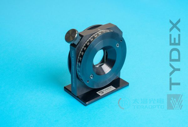
The fundamental calculation methods for broadband phase shifters are well‑known. However, they are not applicable when the measurement system possesses high resolution. Accordingly, we have modified the method to take interference effects into account. A broadband phase shifter consists of several crystalline‑quartz plates oriented at specific angles. These plates are stacked and secured within a mount. According to Jones, an optical system comprising multiple retardation plates is optically equivalent to a system containing only two elements: a so‑called “retarder” and a “rotator” (see Figure 1). The retarder provides the required phase shift (typically π or π/2). The rotator rotates the plane of polarization by an angle ω.
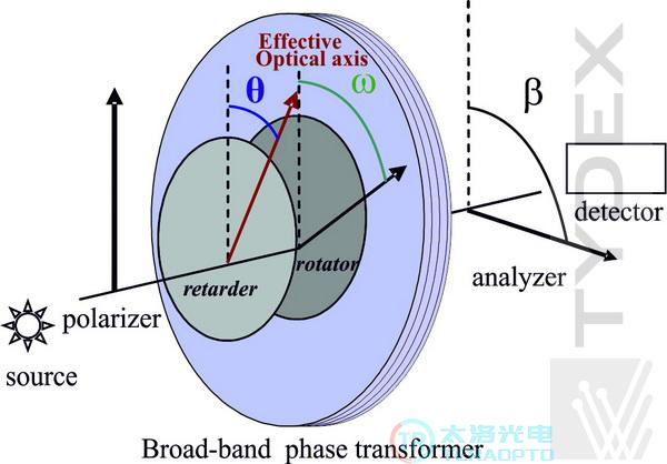
Figure 1. Broadband phase shifter in the Jones formalism and its position relative to the polarizer and analyzer.
Two types of broadband phase shifters are available:
1)ω is not equal to 0° and is wavelength‑dependent. We refer to this device as an “Achromatic Polarization Converter (APC)”. Examples of the ω‑dependence behaviour are given below.
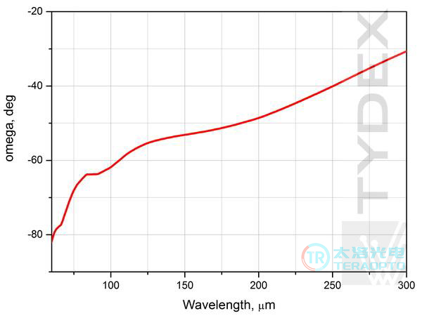
Figure 2. a) APC angle ω/L/4@60-300 um.
2)ω is approximately 0° and remains constant over the operating wavelength range. In this case, it is commonly referred to as an “Achromatic Waveplate (AWP)”, and it operates on the same principle as a monochromatic waveplate.
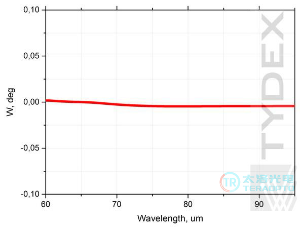
Figure 2. b) AWP angleω L/4@60-95 um.
At present, quarter‑wave achromatic polarization converters, quarter‑wave and half‑wave achromatic waveplates have been developed. There are certain characteristics concerning the positioning of the APC and AWP relative to the polarizer and analyzer (see Figure 1 for details). The APC and AWP shall be oriented at a polarizer angle θ (the effective optical‑axis angle of the APC and AWP). The angle θ exhibits a slight wavelength dependence (see examples below).
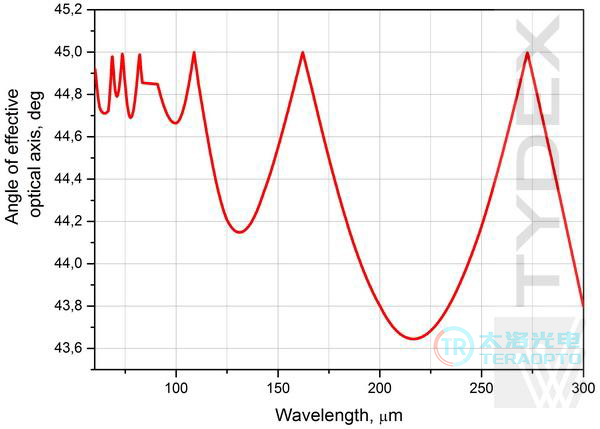
Figure 3. a) APC effective optical‑axis angle θ L/4@60-300 μm.
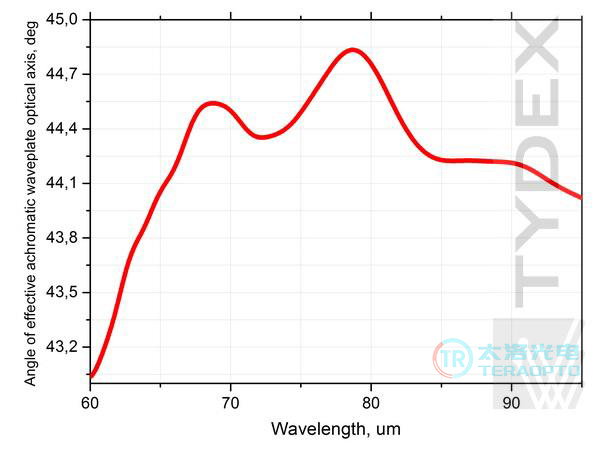
Figure 3. b) Effective optical‑axis angle θ of AWP L/4 @ 60‑95 μm
The axis of the analyzer forms an angle β with the axis of the polarizer (see Figure 1). In the AWP configuration, the position of the analyzer is wavelength‑independent. However, for APC processing, the analyzer shall be adjusted as follows:
1)ω(λ) dependence (see Figure 2a)), when linearly‑polarized radiation is converted into circularly‑polarized radiation;
2)β = ω(λ) ± 45°, for the case where circularly‑polarized radiation is converted to linearly‑polarized radiation.
A negative sign of ω indicates that, when viewed from the polarizer side, the analyzer has to be rotated counterclockwise, opposite to the direction of θ.
In practice, we can design L/4‑AWP, L/4‑APC and L/2‑APC for sub‑intervals in the wide spectral range of 60 μm to 3000 μm. The width of each sub‑range is determined by specific requirements and technical capabilities to realize the target configuration.
Both APC L/4@60‑300 μm and AWP L/4@60‑95 μm were tested using the configuration shown in Figure 1. The θ(λ) dependence of APC and AWP with respect to the polarization axis was taken into account (see Figures 3a and 3b for details). The APC transmission spectra at different analyzer positions were measured with a BrukerVertex 70 FTIR spectrometer (see Figure 4).
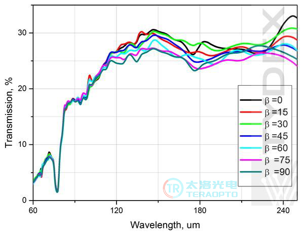
Figure 4. Transmission spectra of APC L/4@60‑300 μm were measured for different analyzer positions.
We selected several wavelengths and plotted a graph showing the dependence of APC transmittance on the analyzer angle (see Figure 5).
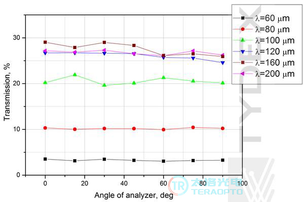
Figure 5. Measured transmittance of APC L/4@60‑300 μm as a function of analyzer angle β.
It can be seen from the figure that the transmittance is independent of the angle (the small data scatter originates from the characteristics of Fourier‑transform measurements). This indicates that the radiation passing through the APC is circularly polarized, confirming the proper operation of the APC.
The optical properties of AWP L/4@60‑95 μm were investigated at the Terahertz Center of the University of Regensburg, Germany, using a high‑power pulsed NH3 laser at 77 μm and 90 μm. Vertically‑polarized and circularly‑polarized laser radiation were measured via the AWP as a function of the analyzer rotation angle. Typical measured signals are shown in Figure 6. Deviations from the ideal O‑shape and figure‑8‑shape do not exceed 10 %. The plots confirm the correct conversion of linearly‑polarized radiation into circularly‑polarized radiation and vice versa.
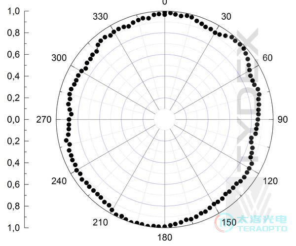
Figure 6. a) Laser radiation intensity as a function of analyzer rotation angle for linearly‑polarized radiation passing through AWP L/4@60‑95 μm.
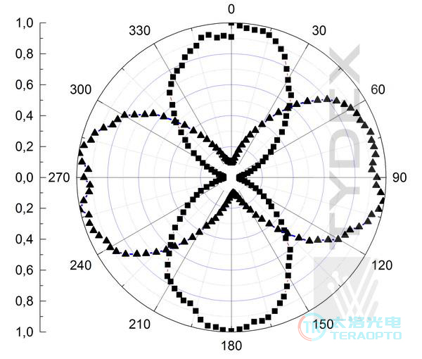
Figure 6. b) Laser radiation intensity as a function of analyzer rotation angle for circularly‑polarized radiation passing through AWP L/4@60‑95 μm.
We conditionally divide achromatic waveplates into two types: short‑wave narrow‑band and long‑wave broad‑band. The short‑wave narrow‑band waveplates operate within a narrow sub‑interval from 60 μm to 200 μm, whereas broad‑band waveplates are intended for wavelengths above 200 μm. A broad‑band achromatic waveplate can be fabricated with an operating frequency slightly above 60 μm. However, its considerable thickness and low transmittance in the 60‑100 μm range must be taken into account. The figure below shows the transmittance spectra of the narrow‑band achromatic waveplate L/2@60‑134 μm and the broad‑band waveplate L/2@60‑300 μm.
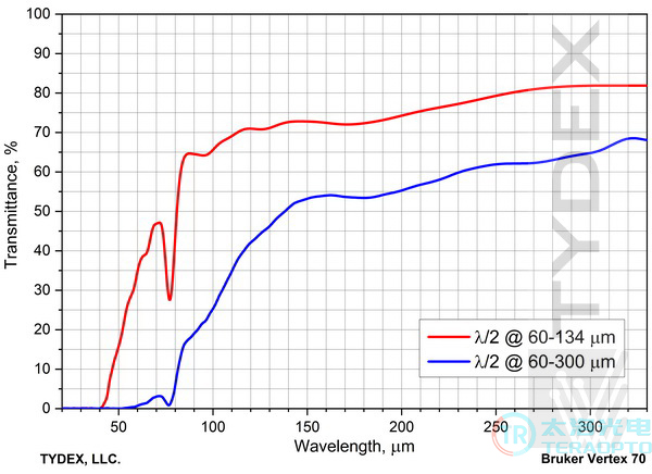
Figure 7. Transmittance spectra of the narrow‑band achromatic waveplate L/2@60‑134 μm and the broad‑band waveplate L/2@60‑300 μm.
The characteristics of the broad‑band waveplate were measured in the setup illustrated in Figure 8. To obtain a collimated THz beam, two condensing THz lenses were placed behind the emitter and in front of the detector. A waveplate and three polarizers were positioned between the lenses. The first polarizer ensures that linearly‑polarized radiation impinges on the waveplate. The second polarizer, also referred to as the analyzer, is located behind the waveplate. Immediately after it is the third polarizer, whose axis is oriented identically to that of the first one. Measurements were performed with the analyzer rotation angle varied from 45° to −45°.
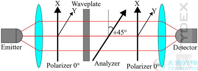
Figure 8. Test setup diagram of the broadband waveplate
Figures 9‑12 present the transmittance and retardation spectra of the quarter‑wave achromatic waveplate in the range of 250‑500 μm, as well as the spectra of the achromatic half‑wave plate over 200‑600 μm.
The results verify that the actual retardation of the quarter‑wave achromatic waveplate is within ±5% of π/2, and the retardation of the half‑wave plate is within 6% of π.
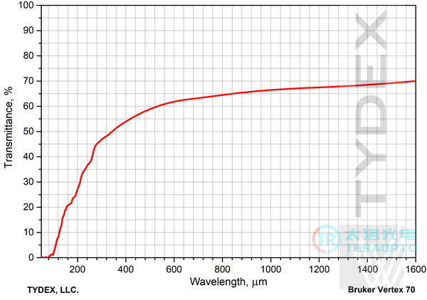
Figure 9. Transmittance spectrum of the broadband achromatic L/4@250-1500um
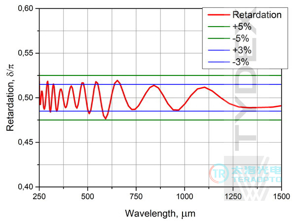
Figure 10. Retardation spectrum of the broadband achromatic L/4@250-1500um
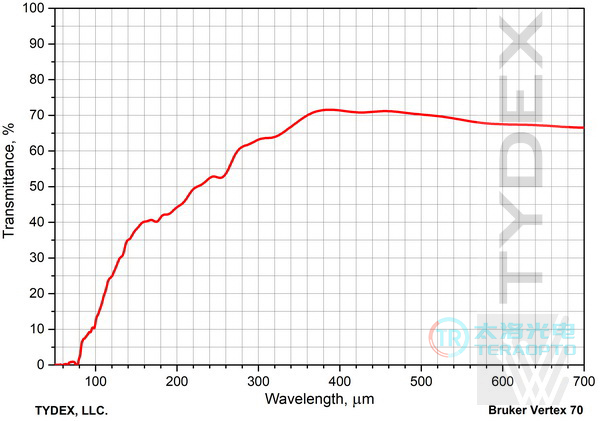
Figure 11. Transmittance spectrum of the broadband achromatic L/2@200-600um
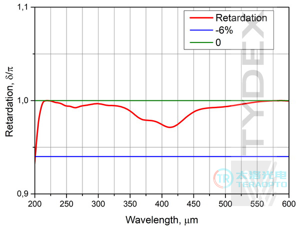
Figure 12. Retardation spectrum of the broadband achromatic L/2@200-600um
General Specifications:
| Achromatic thz polarization converter | Achromatic thz short‑wavelength narrow‑band waveplate | Achromatic thz long‑wavelength broadband waveplate | |||
| retardation | L/4 | L/4 | L/2 | L/4 | L/2 |
| Operating wavelength range,μm | 60-300* | 60-95* | 60-134* | 250-1500,300-1500,375-1500,500-1500,750-1500 * | 200-600,500-1500,750-1500 * |
| Conversion error,% | +/- 15 | +/- 10 | +/- 10 | +/-3..5 | +0/-6 |
| Clear Aperture | 25 (standard) or<25 (custom) | ||||
| Holder | Standard or Rotating Mount | ||||
| *Or Customer‑Specified | |||||
Achromatic polarization converters and achromatic waveplates are manufactured upon request.
Broadband THz Waveplate Documentation Download
>>Download THz Broad-band Phase Transformers Datasheet (PDF, 360 KB)