
EN
EN
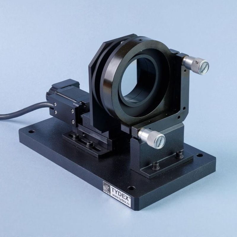
THz Scanning Fabry-Pérot Interferometer, THz Frequency Measurement System
Product Introduction
The THz Scanning Fabry-Pérot Interferometer/Terahertz Wavelength Tester (Terahertz Frequency Measurement System) is a specialized instrument designed for measuring THz wavelengths and calibrating narrowband THz radiation wavelengths or frequencies. The terahertz scanning F-P interferometer consists of two parallel semi-transparent silicon mirrors, one of which is mounted on a linear motor and can measure corresponding THz wavelength data by controlling the distance between the mirrors.
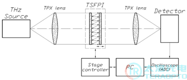
Schematic diagram of a terahertz frequency measurement system
TSFPI can be used with the following light sources:
• Gyrotron;
• Light-pumped submillimeter-wave laser;
• Cacinotron BWO;
• Free electron laser;
• Differential-frequency THz generator;
• Optical mixing THz generator;
• Quantum cascade laser;
• P-Ge laser;
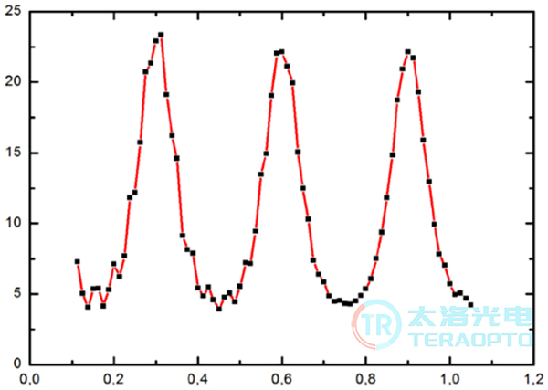
This interferometer can also be used to measure the wavelength and intensity of broadband terahertz radiation sources, and to filter terahertz radiation based on the transmission spectrum of a Fabry-Péron interferometer (as shown above). The transmission spectrum of TSFPI measured with the Menlo Systems TERAK8 terahertz time-domain spectrometer at a mirror spacing of 500 micrometers. The terahertz-scanning Fabry-Péron interferometer TSFPI supports various mirror translation modes, including moving mirrors to specified positions, translating over designated distances, continuous translation, and cyclic translation. The mirror translation speed, translation interval, starting position, and ending position are all adjustable.
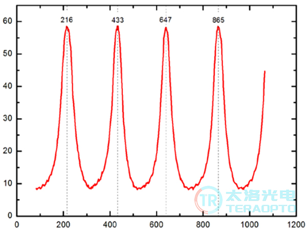
The figure above illustrates the relationship between the signal amplitude of the Tydex GP-1P photoacoustic detector and the distance between TSFPI mirrors (Note: Terahertz radiation is generated by a light-pumped submillimeter-wave laser with a wavelength λ_las = 432 μm). The horizontal axis represents the mirror spacing in micrometers; the vertical axis represents signal amplitude in millivolts. As shown in the figure, the distance between adjacent TSFPI transmission peaks is approximately 216 micrometers (433 μm – 216 μm = 217 μm; 647 μm – 433 μm = 214 μm; 865 μm – 647 μm = 218 μm), which corresponds to half of the laser wavelength. This result aligns with the theoretical formula for TSFPI transmission peaks: λ = 2 * d/m, where d is the TSFPI mirror spacing (in micrometers), m is the order of interference, and λ is the measured wavelength (in micrometers).
Parameter Specifications:
Parameter | TSFPI-1 | TSFPI-2 | TSFPI-RF-1 | TSFPI-RF-2 |
Operation wavelength | 0.1-15 THz | 0.1-15 THz | 0.02-15THz | 0.02-15THz |
Free Spectral Range | 0.01-1.8 mm | 0.01-1.8 mm | 0.01-1.8 mm | 0.01-1.8 mm |
Mirror lens spacing | 0-9.5 mm | 0-9.5 mm | 0-29.5mm | 0-29.5mm |
Displacement Accuracy | ±1.25 um | ±1.25 um | ±1.25 um | ±1.25 um |
Beam Height | 53 mm | 110 mm | 53 mm | 110 mm |
Clear aperture | 26 mm | 52 mm | 26mm | 52mm |
Size(L*H*W) | 150 х 90 х 112 mm3 | 232 х 151 х 120 mm3 | 150 х 90 х 112 mm3 | 232 х 151 х 120 mm3 |
Weight,kg | 2.3 | 2.5 | 2.4 | 2.7 |
Main Features:
• The device operates across a wide frequency range;
• High breakdown threshold;
• Large aperture: up to 52 mm;
• High mirror positioning accuracy:±1.25 μm;
• Easy to use.
Optional Accessories:
GC-1P/T/D type photoacoustic detector (Golay cell);
Bandpass filter (BPF): Suitable for specified wavelengths in the range of 0.1–15 terahertz;
Infrared low-pass filter (LPF): Cut-off frequencies available include 23.4 THz, 23.3 THz, 23.1 THz, 14.3 THz, 10.9 THz, 8.8 THz, 5.5 THz, 4.3 THz, 4 THz, and 3.2 THz;
Attenuator kits: with transmission rates of 1%,3%,10%, and 30%;
TPX lenses and high-resistance zone-fused silicon (HR FZ-Si) lenses.