EN
EN
THz Array Antenna,Large-Area Excitation Of THz Emitter
Product Introduction
The photogalvanic antenna thz emitter excited by femtosecond laser pulses is a commonly used light source for single-cycle thz radiation pulses. By adopting a finger electrode structure, we significantly improved the emitter efficiency and thz output power. To avoid the destructive interference of the thz sub-waves generated by electrons accelerating in opposite directions, the second metal layer (the green part in the figure) can suppress the photogenerated carrier process at every other gap of the electrodes. The emitter based on this patented design can be purchased from Shanghai Tera photoelectric Technology.
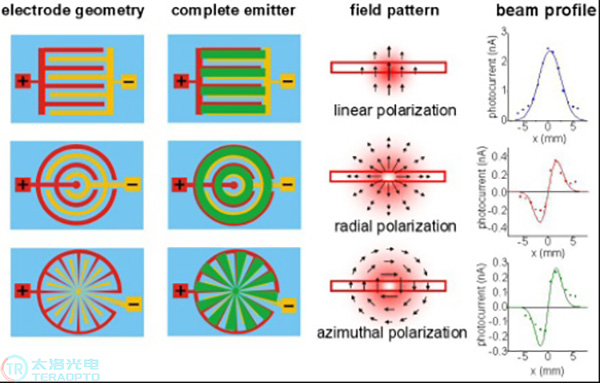
The scalable thz emitter provides flexibility for electrode structure design, enabling the generation of modes different from the commonly used linearly polarized Gaussian beams. We have achieved the generation of radial and angularly polarized thz beams using photoconductive emitters. Among them, the radial polarized beam has unique advantages: compared to the linearly polarized beam, its focused spot size is smaller, and there is a longitudinal field component at the focus.
By using non-polar material germanium (Ge) instead of the traditional III-V group semiconductors as the photoconductive material, since there is no residual radiation band (Reststrahlenband), an extremely wide thz bandwidth of up to 70 thz can be achieved.
Characteristics of THz Array Antenna
——> Large-area scalable emitter based on semi-insulating gallium arsenide (GaAs)
——>Operation is simple: Just place it in the near-infrared beam of the transmittance geometric structure.
——>Suitable for generating strong single-cycle thz pulses, it is an ideal choice for nonlinear thz spectroscopy.
——>The thz field strength and spectral width depend on the excitation laser system and the detection system. If a strong laser pulse is used for excitation, the laser spot size on the emitter needs to be controlled to avoid saturation. The typical parameters are shown in the table below.
The observed thz amplitude is highly dependent on multiple parameters of the entire thz time-domain spectroscopy system, especially the laser pulse duration, the detection crystal, and the focusing optical element. Using the TeraSED-10 device, the parameters listed in the left column (the guaranteed values) can be easily achieved without any additional operations. Under optimized configuration, higher parameters can be achieved (see the values in parentheses).
THz Electric Field Intensity | Excitation Light Pulse Energy | Intensity Spot Size | THz Electric Field Intensity |
0.1kV/cm-0.3kV/cm | 10nJ | 0.3mm | 0.1kV/cm-0.3kV/cm |
5kV/cm-17kV/cm | 4uJ | 1mm | 5kV/cm-17kV/cm |
THz Array Antenna parameters
Bias Voltage | Bias Type | Maximum Duty Cycle | Maximum Excitation Power @ 300um Focused Spot |
10V | DC | NA | 200mW |
±10V | Pulse | 50% | 200mW |
15V | Pulse | 25% | 600mW |
Excitation Light parameters* | |||
Repetition Frequency | Pulse Width | Wave Length | Exciting Power |
≥50MHz | ≤200fs | 760nm-820nm | Depends on the repetition frequency and the size of the light spot |
*This model antenna can also be excited by an amplified laser pulse. The usage method should be consulted specifically according to the parameters of the laser device
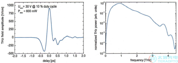
The typical thz time-domain spectrum and frequency spectrum of the thz array antenna, with the detection end being a 110cut,25um thick ZnTe crystal
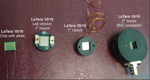
Different packaging forms of thz array antennas